GROUP 3
ezzaty nordin
ain
nabila amirah
ummi
siah
jamilah
farahin
nabilah syahirah
chau
azlina
asilah
DFP5043 – Software
Requirement and Design
Tutorial Lab4
Instruction:
Discuss and contribute
together to answer
the questions below and
post the answer to the class’s blog.
Don’t forget to write
your name in the blog.
Define and draw example
of architectural design and models of software architecture below,
i.
Architectural Design
ii.
Logical View
iii.
Process View
iv.
Development View
v.
Physical View
vi.
Scenario
ANSWER:
i.
Architectural Design
·
Architectural
design is a concept that focuses on components or elements of a structure. An
architect is generally the one in charge of the architectural design. They work
with space and elements to create a coherent and functional structure.

ii.
Logical View
Logical view: The logical view is
concerned with the functionality that the system provides to end-users. UML
diagrams used to represent the logical view include, class diagrams, and state
diagrams or which shows the key abstractions in the system as objects or object
classes.

iii.
Process View: The process view deals with the dynamic aspects
of the system, explains the system processes and how they communicate, and
focuses on the runtime behavior of the system. The process view addresses
concurrency, distribution, integrators, performance, and scalability, etc. UML
diagrams to represent process view include the activity diagram.

iv.
Development view
- · The development view illustrates a system from a programmer's perspective and is concerned with software managementThis view is also known as the implementation view.It uses the UML Component diagram to describe system components.
- · Viewer : Programmers and Software Managers
- · Considers : Software module organization ( Hierarchy of layers, software management, reuse, constraints of tools )
- · What this view shows? “This view shows the building blocks of the system”.
- · UML diagram : Component, Package diagrams

v.
Physical View
The physical
view depicts the system from a system engineer's point of view. It is concerned
with the topology of software components on the physical layer as well as the
physical connections between these components. This view is also known as the
deployment view. UML diagrams used to represent the physical view include the
deployment diagram. The other name for physical view is deployment view model.

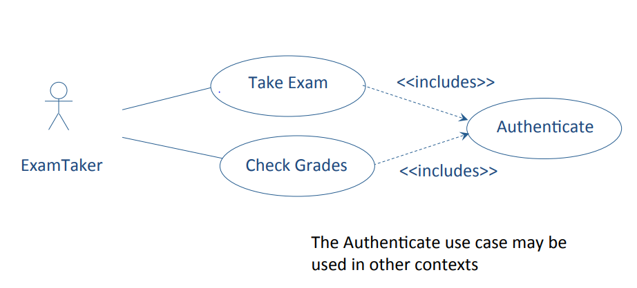
vi.
Scenario
The description of an
architecture is illustrated using a small set of use cases, or scenarios, which
become a fifth view. The scenarios describe sequences of interactions between
objects and between processes. They are used to identify architectural elements
and to illustrate and validate the architecture design. They also serve as a starting
point for tests of an architecture prototype. This view is also known as the
use case view.
- - EXAMPLE OF USE CASE SCENARIO
Name of Use Case: Take Exam Actor(s): ExamTaker
Flow of events:
- ExamTaker connects to the Exam server.
- Exam server checks whether ExamTaker is already authenticated and runs authentication process if necessary.
- ExamTaker selects a exam from a list of options.
- ExamTaker repeatedly selects a question and either types in a solution, attaches a file with a solution, edits a solution or attaches a replacement file.
- ExamTaker either submits completed exam or saves current state.
- When a completed exam is submitted, Exam server checks that all questions have been attempted and either sends acknowledgement to ExamTaker, or saves current state and notifies ExamTaker of incomplete submission.
- ExamTaker logs out.


Comments
Post a Comment