ARCHITECTURAL DESIGN AND MODELS OF SOFTWARE ARCHITECTURE

i.
Architectural
Design
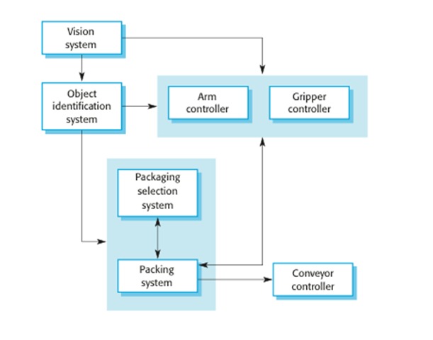
Architectural
design is the initial stage of the process for designing the system. It is also
a relationship between the specification and the design process. Usually done
in parallel with some specification activity. It involves identifying the main
system components and their communication.
ii.
Logical
View

Logical view
is the services that the system provides to end-users depicted with UML model
types: Class diagram, Communication diagram, Sequence diagram .
iii.
Process
View

Process view
is the process view deals with the dynamic aspects of the system, explains the
system processes and how they communicate, and focuses on the runtime behaviour
of the system. The process view addresses concurrency, distribution,
integrators, performance, and scalability, etc.
iv.
Development
View

Development
view is he system from a programmer's perspective, concerned with software
management. This view is also known as the implementation view. It uses the UML
Component diagram to describe system components. UML Diagrams used to represent
the development view include the Package diagram.
v.
Physical
View

Physical
view is the physical view depicts the system from a system engineer's
point-of-view. It is concerned with the topology of software components on the
physical layer, as well as the physical connections between these components.
This view is also known as the deployment view. UML Diagrams used to represent
physical view include the Deployment diagram.
vi.
Scenario

Scenarios is
the description of an architecture is illustrated using a small set of use
cases, or scenarios which become a fifth view. The scenarios describe sequences
of interactions between objects, and between processes. They are used to
identify architectural elements and to illustrate and validate the architecture
design. They also serve as a starting point for tests of an architecture
prototype. UML Diagram(s) used to represent the scenario view include the Use
case diagram.
Reported by :
- Aida
- Aina
- Atifah
- Atiqah
- Asyikin
- Ilmi
- Khairunnisa
wow amazing
ReplyDeleteFuh hebat lagi bergaya
Deletethanks for the information !
ReplyDeleteit really helpful
ReplyDeleteNice!
ReplyDeletewow, thanks for this posting ^^ . (Kau buat ku terpaku sepertinya diriku yg mahu diri kamu dan bilaa...)
ReplyDeletekau hadir bagai satu misteri
Deleteternyata dirimu
DeleteBegitu berharga
DeleteI love the sentence. Simple <3
ReplyDeleteHebat informasi nya
ReplyDeleteThanks for sharing.
ReplyDeletecustomized purchase software management